Mission 7 of the International Aerial Robotics Competition
I was a co-lead and core technical contributer to the Pitt’s International Aerial Robotics Competition (IARC) in 2017 and 2018. As summarized on the Pitt RAS project page. “The IARC is an annual competition requiring teams to develop aerial robots that solve problems on the cutting edge of what is currently achievable by any aerial robots, whether owned by industry or governments. Mission 7 involved developing an autonomous drone capable of interacting with randomly moving robots on the ground to direct them towards a goal”.
In 2017 the team had the Most Points and won Best System Design at the American Venue. In 2018, the team repeated these succeses and also received the Best Technical Paper award. Mission 7 was completed by Zhejiang University in 2018 at the Asian-Pacific venue.
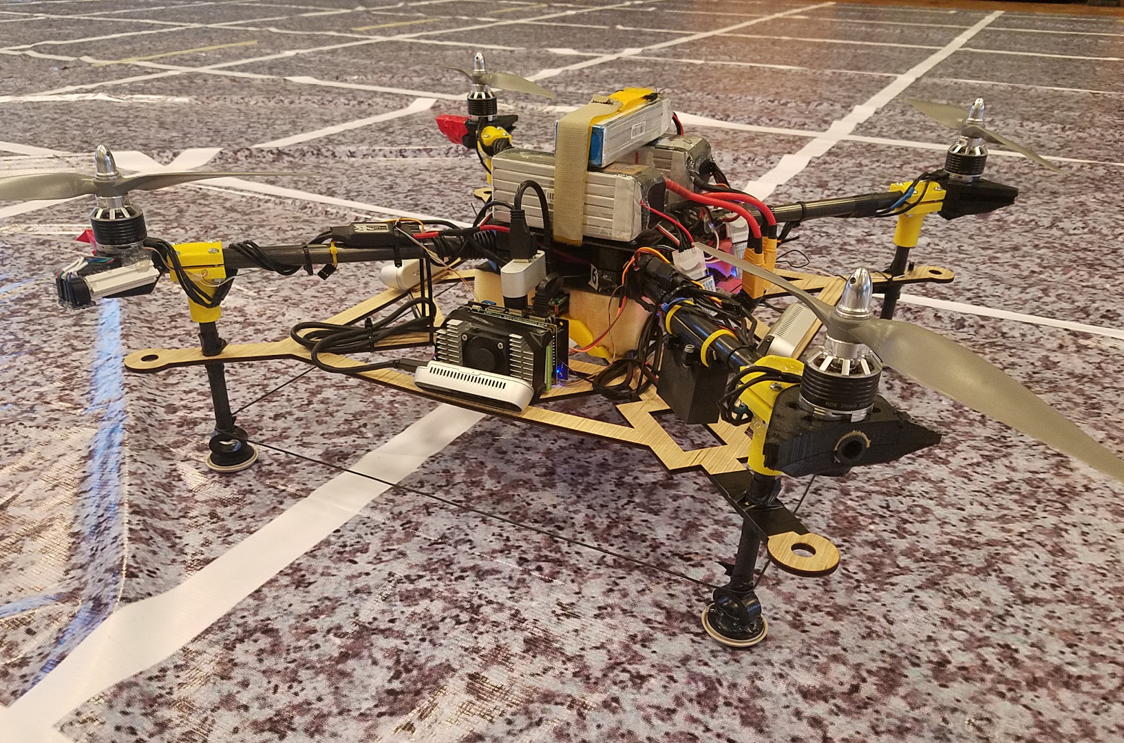
The team produced substantial software, hardware, and electronics as over 30 students contributed to create an entirely custom UAV. Many major systems including flight control, obstacle detection, and computer vision algorithms were specially designed for this mission. ROS and OpenCV were used extensively; over 10 ROS packages were created along with numerous ROS nodes.
At home the team demonstrated target interaction, obstacle avoidance, navigation, and control using the custom software stack. At competition in 2018 everything except target interaction was demonstrated. Technical gremlins (primarily lighting problems) wreaked havoc on the last days of testing making it impossible to test target interaction in the final days.
Main Personal Contributions
My work focused on controls and state estimation, however I was involved in electronics and mechanical design as well. The subsystems I focused on are listed below. For more details, the appropriate section of the Technical Postmortem is linked.
Controller and Optical Flow Plot
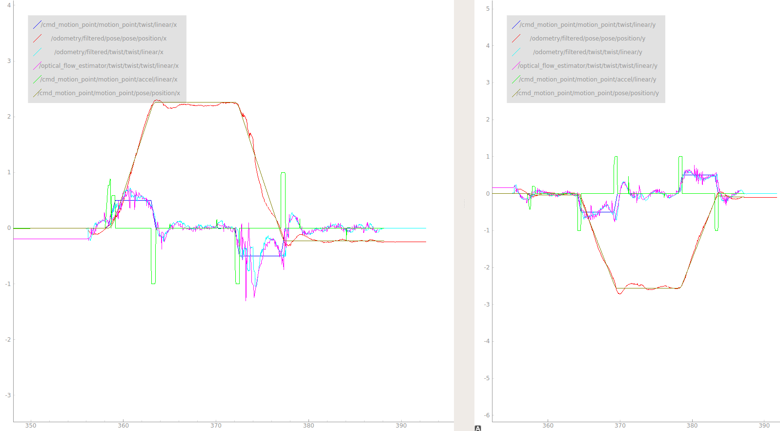
Graph showing controller and flow estimation performance when flying a 2 meter square formation
Legend is at the top right, the X axis is in seconds, Y axis is in meters, meters/sec, or meters/sec^2 as appropriate
The overall performance of the control and estimation systems described below are shown in the above figure. It depicts achivement of X and Y position and velocity targets, estimates of velocity and position from the kalman filter, and raw estimates of flow coming from the optical flow estimator.
Controls
Time Variant, Non-linear Rotor Thrust Modeling
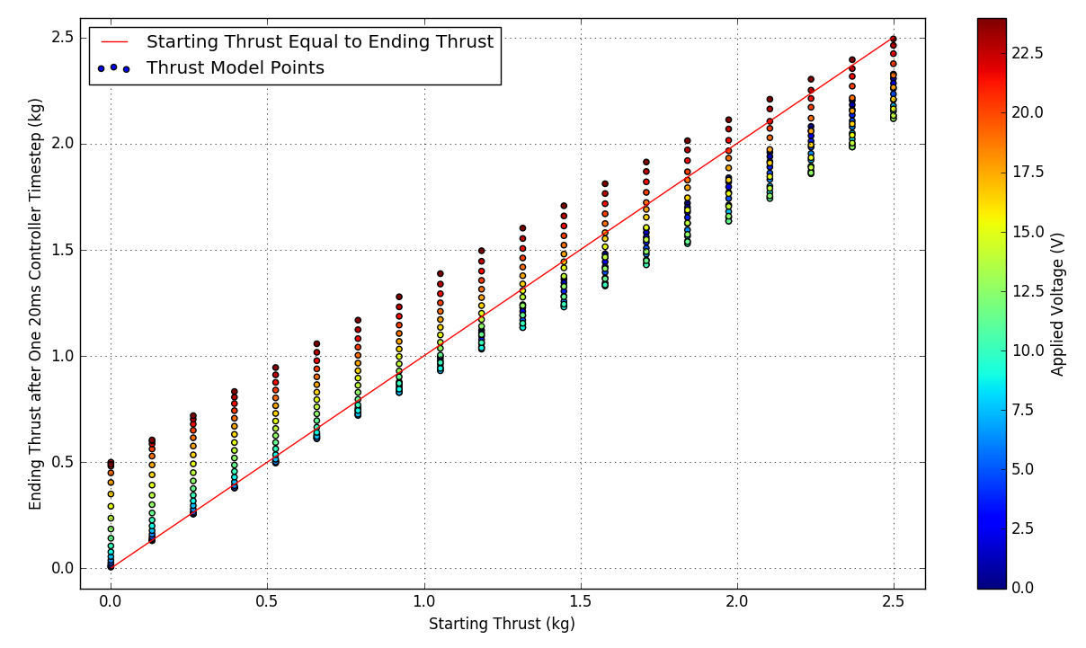
Operating a 5 kg UAV quickly required an accurate model of the propulsion system. A innovative method was created which allows for accurate predicions to be made in an open loop manner using presolved discretized models. Technical Postmortem Section
This model was discussed in the 6 Degree of Freedom UAV Thrust Model Summary available on the publications page.
Motion Profile Controller
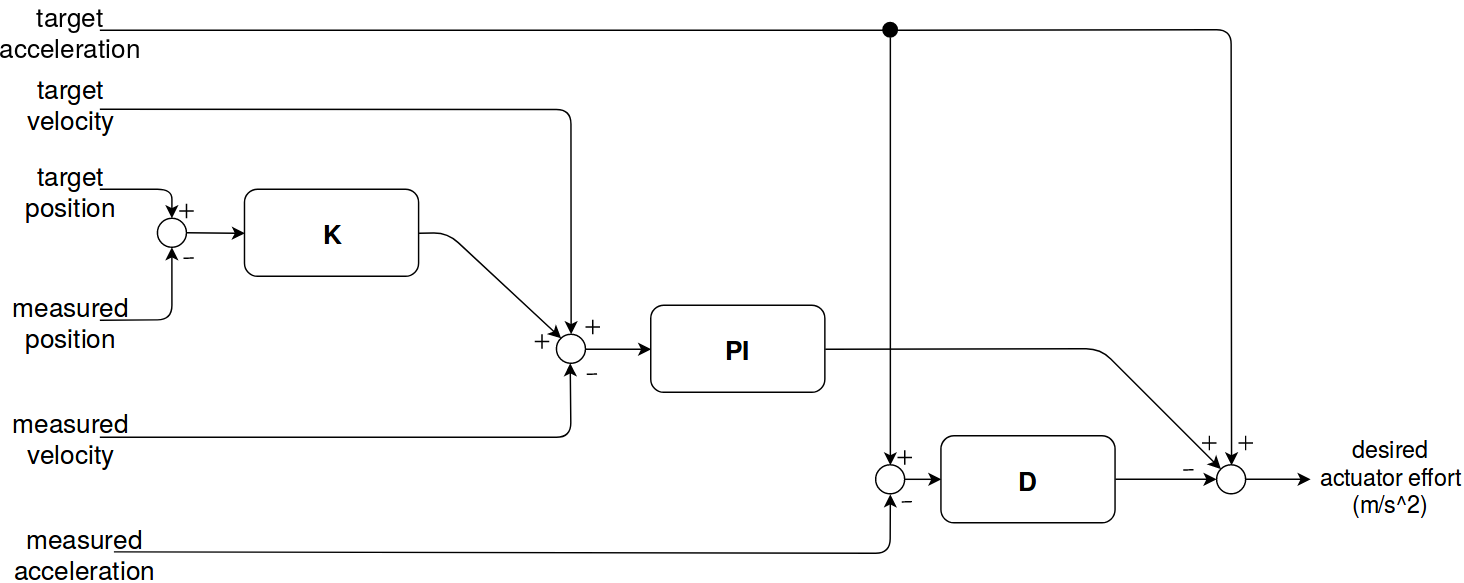
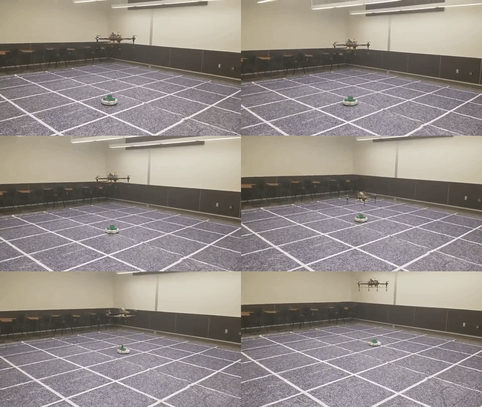
In order to support a responsive interactions with moving targets, a custom linear controller was created. Due to the accuracy of the thrust model used, it was possible to specify acceleration setpoints directly. This was crucial for accurately and repeatedly interacting with the moving targets. Technical Postmortem Section
Flight Controller
A cleanflight based flight controller was used. This was contrary to the conventional wisdom of using a Pixhawk with either PX4 or Ardupilot. However, this decision allowed us to use custom controller more suited to the IARC Mission 7. Technical Postmortem Section.
State Estimation
Texture Classification for Boundary Detection
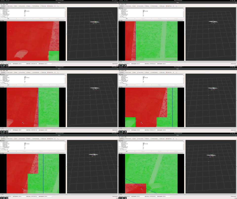
In order to remain within arena boundaries, a method of detecting areas as outside of an arena was required. A texture classifier was created using Tensorflow for this purpose. Technical Postmortem Section
The above video shows the UAV using the boundary detector to “bounce off walls” similar to an old-fahsioned screensaver.
Optical Flow
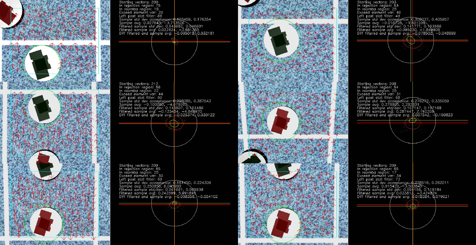
(Right) Visualization of statistical filter used to filter flow vectors
A custom velocity estimation system was implemented using OpenCV’s implementation of Lucas-Kanade optical flow with pyramids. It was coupled with a statistical filter which detected outliers based on the variance of the two dimensional distribution of the flow vectors. The technique allowed vectors to be ignored that were known to be on the top of moving targets.
The flow estimated was combined with other sensors in an EKF (robot localization), a few minutes a flying would only result in approximately one meter of drift. Velocity estimates were within accurate to within 5 cm/s. Technical Postmortem Section
Electronics
30V 30A eight channel DC Circuit Breaker Safety System for 6DOF UAV
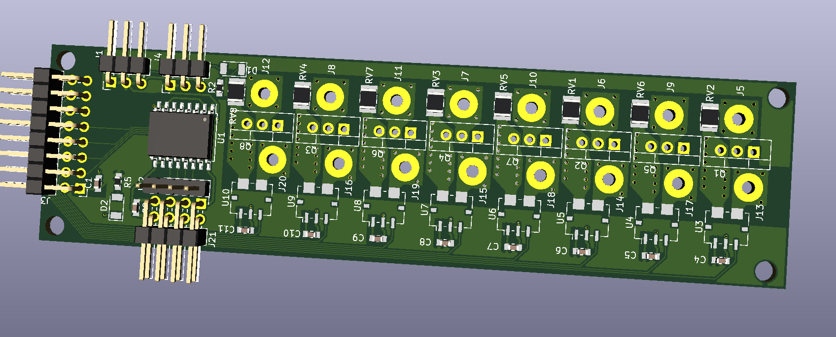
A 7 kg 6 DOF UAV was designed and built, however software did not have time to make the transition to the new airframe for the 2018 competition. The above circuit breaker was designed and built for this UAV. Technical Postmortem Section
